Rudder Part I
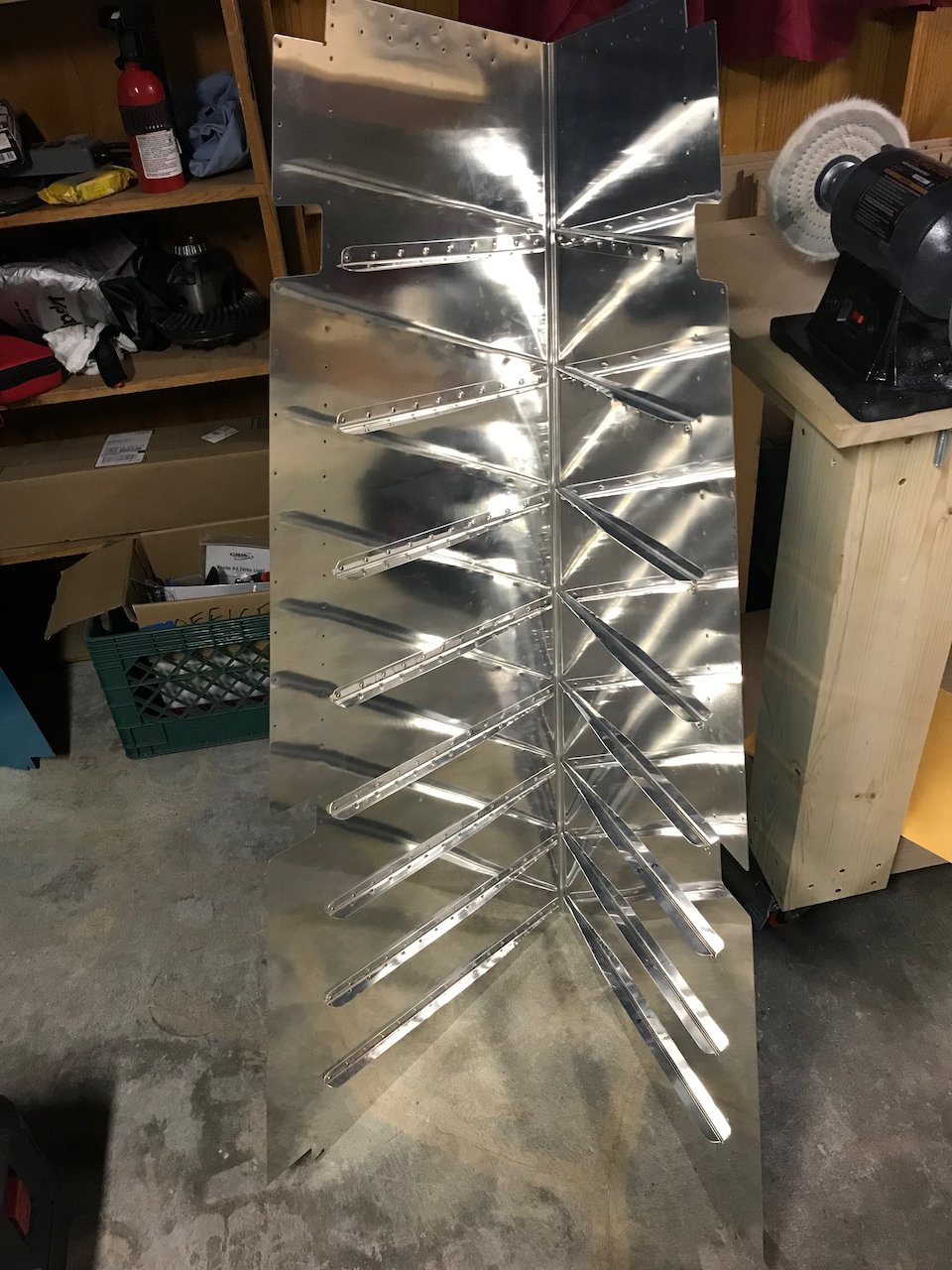
Started on the rudder before thanksgiving and took a couple days off to go home for the holiday. The rudder starts with cutting and deburring the stiffeners, which is a pretty repetitive and boring task. Normally you would cleco the stiffeners to the skin, final drill the holes, take everything apart, and then deburr and dimple the skin and all the stiffeners. I saved all the final drilling and deburring by using a dimple die set I got from Synergy Air when I was up in Oregon a couple months ago taking a class. The dimple die is designed to enlarge the pre-drilled hole so there is no need to final drill or deburr. All you need to do is dimple. This die set is approved by Van’s for this purpose. Then I back riveted the stiffeners to the skin.
The stiffener rivets closest to the trailing edge are pretty hard to get using back riveting unless you bend the skin a pretty significant amount. I didn’t want to risk damaging the skin by bending it so far so elected to use a bucking bar to set those rivets.
I then bent the trailing edge using a break I made from some 2x8s and some door hinges. I bend it most of the way but am holding off to do the final bend. I bought the straightest 2×8 at home depot that I could find but it is still bow’d a tiny bit and is bending the skin slightly uneven. I’m going to try to flatten out the board before I do the final bend.
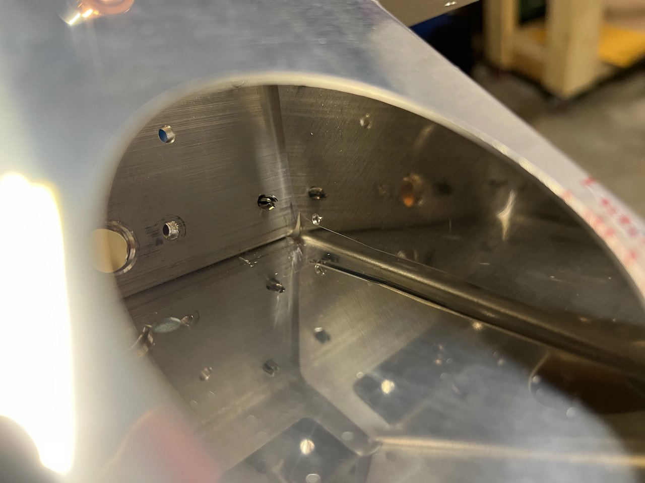
Next was to build up the spar assembly. This part was relatively straight forward until it came to the rudder horn brace. The drawings show a specific cut line on where to trim the bracket, but if you trim on that line, you WILL take too much material off and not have enough edge distance when you drill your rivet holes. A friend from work that has previously built this tail kit warned me of this, so I made sure to leave a little extra room. Well, I still didn’t leave enough room and ended up having no edge distance for the rivet. I was super lucky that my friend happened to have an extra rudder horn brace laying around from his build that he let me have. I cut about 1/8″ – 1/4″ past the line that Van’s quotes for this one and it worked out well. There is a marking hole in the middle of the cut that I could not cut out completely but instead had to smooth out. (The pictures show it more clearly) Once this new rudder horn brace is cleco’d up, I will be ready to start cleco’ing the assembly to the skin.